We had two work sessions in March, the 3rd and 5th. Most of the efforts were devoted to installing the needle beams as described in the previous post.
There were more holes to drill. Existing holes were present in the sills but these had to be re-drilled through the steel angles that had been placed earlier. Don and John are manning the drill.
This photo shows the bolts in place along the length of the needle beam where they have been placed through the sills. Bill K. is tightening one of the nuts. The truss rod has been put in position but not engaged with the queen posts or tensioned as yet.
Tom then cut the protruding ends of the bolts with his portable band saw.
Spacer plates were cut from stock to place between the beam and the intermediate and outer sills as the angle steel on the inner sills caused the beam to be lowered by the thickness of the steel. Fortunately there was an easy way to do this with a mechanical saw.
The end bolts for the needle beams presented another challenge. Notice at the far right side of this photo one of the vertical framing pieces has been cut and removed. In the lower right corner a groove is present in the large plank where it meets the outer sill. This is where the two end bolts were for the needle beam. Part of the framing on the outside of the car had to be removed to access this area as well.
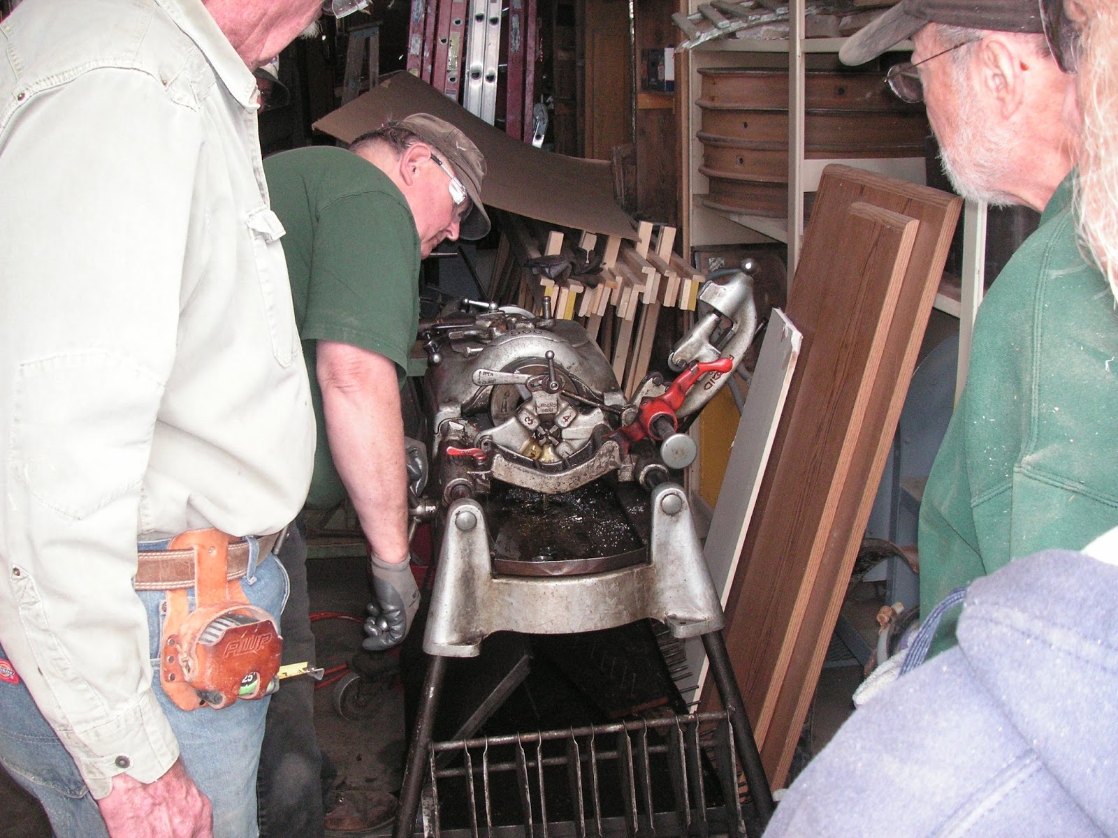
The solution was to use rod threaded at both ends inserted from the bottom. Here one of the rods is being threaded by hand.
Here is yours truly at the bottom. Getting the bolts through the beam, spacer plates, and sill was a bit tricky, but finally accomplished.
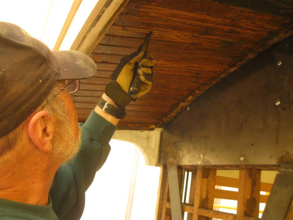
Then making room to thread nuts on the bolts was necessary. Bill K. is wielding the chisel.
This photo shows the two end bolts in the needle beam secured. Note the cut end of the framing member near the top of the picture. The next task was to replace the framing that was removed for access.
This photo shows the needle beam with the two bolts through it and secured with a plate between the nuts and the beam. There is an end cap over the beam with the truss rod passed through it and a nut to tension the rod.
Here is the final configuration with the truss rod in the grooves of the queen posts providing support to the center of the car.
The next step was to repair the damage caused by obtaining access to needle beam bolts. Don is gluing the pieces together on one of the verticals that was cut. Amazingly the cut piece didn't get lost.
Then metal plates were fastened to each side of the splice.
Finally the frame bracing that was removed was replaced. Some of the pieces that were removed had to be replaced with new wood since they were damaged.
Concurrently, Bob was working on plugging the screw holes in the window sills. Here he is cutting plugs out of a block of wood using Craig's plug cutter.
The plugs were then glued into the screw holes like so.
The plugs were then cut flush with the window sill using a fine saw with no kerf so as not to scratch the sill.
Finally, Bill L. continued work on removing paint from the overhangs. First with a heat gun,
then with a scraper. Looking good, Bill.


