Friends COS calendar

A subset of the Friends of the Cumbres and Toltec Scenic Railroad located in Colorado Springs, Colorado, with the mission of preservation, restoration, and interpretation of CTSRR historic assets. The Springs group is primarily involved in restoration. See below for blog archive of older postings.

Thursday, December 6, 2012

Multi-tasking - 12-1-12

One of the tasks today was to replace the stabilizing blocks in the frame of 470.  Many of them were servicable and were left in place, but many had to be removed.  Craig obtained the lumber and planed it to the proper thicknes to fit in the grooves of the framing.  In this photo John and Craig are discussing the process.  Craig brought his nail gun which he is holding that sped up the process.


John kindly took a picture of me sanding the frames prior to glueing the blocks in place.  There was some residual of the hide glue used initially that was removed, as well as roughing the surface for better adhesion.  The grooves for the blocks can be faintly seen in the vertical member of the framing to my left.


In this photo, Bob is cutting the blocks to fit.  There was some variation in size of the openings, as well as shape where the angled braces are located.


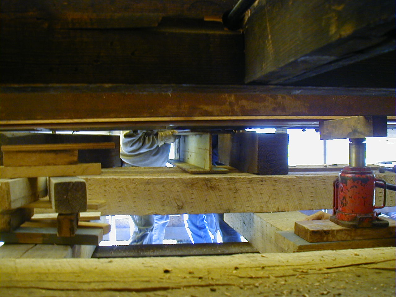
The blocks were both nailed and glued in place, with glue placed around the periphery as on the small triangular blocks stacked below.


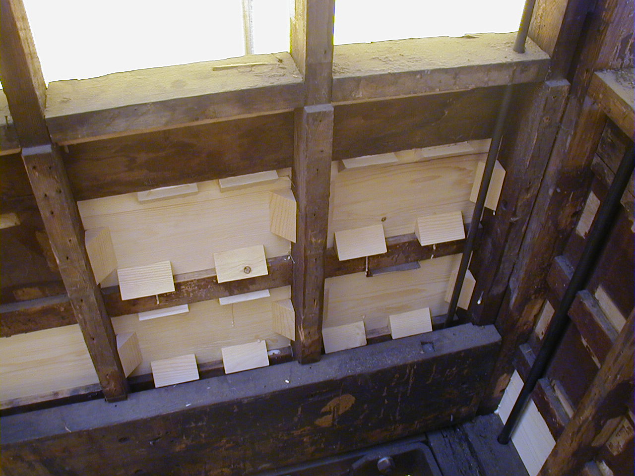
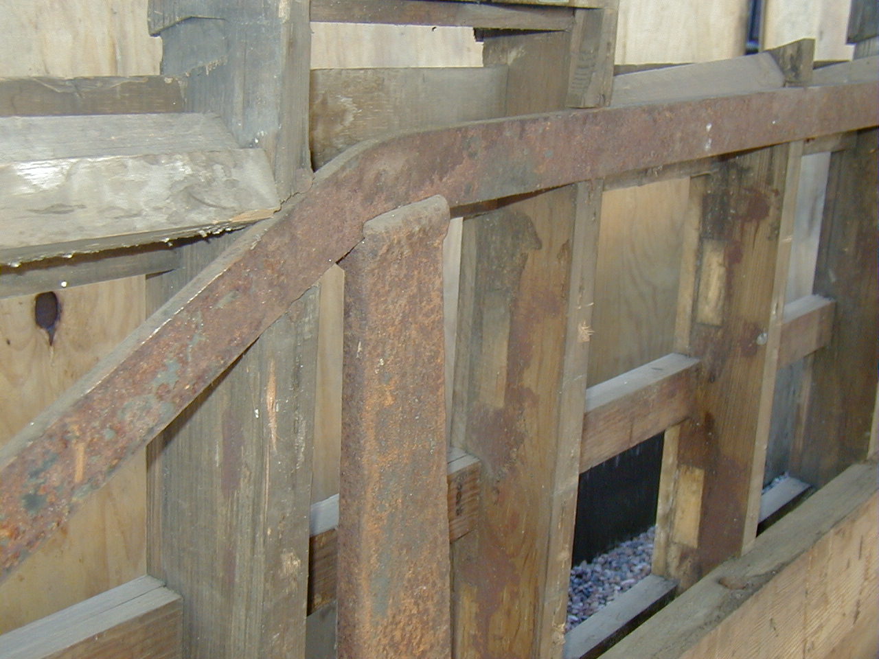
This photo (taken by John) shows the blocks in place from the inside of the car.  Originally they were only glued, not nailed.


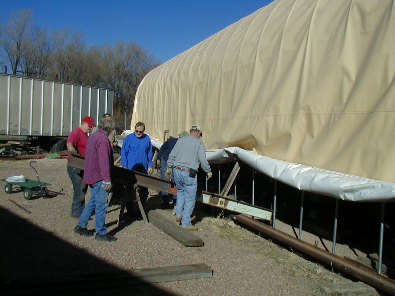
Meanwhile Lenny, John, Tom, and Glenn were involved with steel issues, preparing for securing the steel pieces to the inner sills.  Here Lenny is doing some measuring near the splice in one of the inner sills.


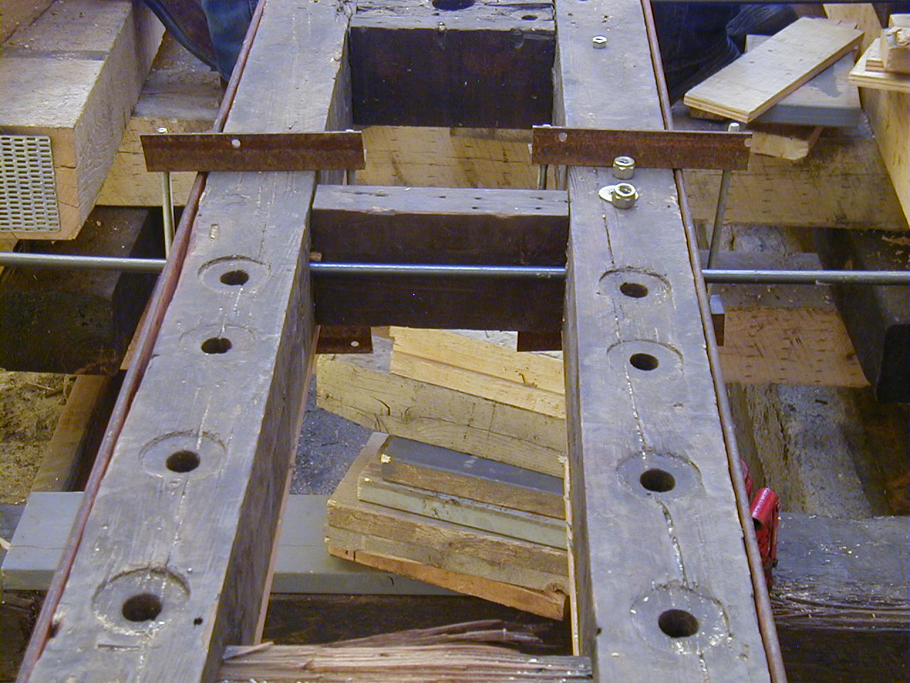
Tom S. has been busy fabricating a prototype assembly for fastening the inner sills together.  John and Glenn are evaluating the device, and it looks like Tom is on the right track.  The bolts are 3/4 X 18-1/4 heavy hex bolts inside schedule 80 pipe which should secure the sills together.

I-beams - 11-17-12

 Today we continued with levelling and straightening the car.  We placed I-beams under the frame at about where the bolsters (trucks) will be as a base.  This meant rolling up one side of the structure as shown in the photo.  Fortunately we had a good crew to lift, and we have one end on a sawhorse in this photo.
In the second photo, the beam is levelled and we are starting to slide it over the ties and under the car frame.  Thanks to Regis from the Trolley Museum who was cheering us on, we have some photos while I was helping lift and shove.
Here John and I are helping to slide the beam in from inside the tent.  We have help on the other side of the car.

This is the view from below.  The beam rests on the ties that have been blocked up from the rails installed initially, and jacks were used to make room for the beams.

Tom is manning one of the jacks at the end of the car.  The ends tended to droop due to the flexibility of the frame, and had to be levelled.

Here is the same thing from the other side with John M. and Tom F.supervising.

Monday, November 12, 2012

Same drill 11-3-2012

Drilling continued in the steel for the north inner sill.  Lenny is doing the honors with the piece in situ, using the drill in the horizontal position, while Bob is providing the lubricant.  The splice piece had already been drilled, but not the long pieces.
Both inner sills have now been fitted with the reinforcing steel.  They will eventually be bolted together with pipe spacers between for added stabilization.  The tie rods passing through the sills will be tensioned later as well.
Meanwhile, Craig is fitting the corner post for the west door that he has fabricated.  The steps into the car were also reinstalled at this end so we don't have to walk to the other end, often ducking extended tie rods, to access the car.

Friday, November 2, 2012

South sill steel fitted 10-20-2012

We started by marking the holes to be drilled for the splice in the two long pieces of steel on the south inner sill.  They were then removed from the sill and lined up for drilling and bolting the splice in place.  Not shown, but taking significant time was the process of moving the tie rods that were passing through the lower sills and the steel, from side to side in order to remove the steel beams.

The magnetic drill was again  used to drill the holes for bolting the splice piece to the larger pieces.  John M. is doing the honors while John E. and Tom are advising.  Craig in the background can't stay away from the wood.
One side is together and the other is ready to bolted.  It has been decided to bolt and weld the steel together after consulting engineers on the best way to do it.  On a prior post I had suggested that bolts alone were going to be used, but they will be welded as well.

The steel that now runs the length of the car weighs over twice as much as the two pieces before joining, so it took a come-along and some coaxing to get it back in place.  Craig is drilling holes to accommodate the heads of the bolts in the sill after the steel is in place.  Finally it all fits together.

With the steel removed, the sills are sagging as well as shifted side to side as in the photo on the left.  After clamping the steel in place on the south inner sill, the alignment is much improved as in the photo on the right.  Note the splice in the sill (done in the past) near the end of the steel on the left is aligned much better on the right.

Friday, October 12, 2012

Bridging the gap 9-15-12

A piece of angle steel as shown above will be used to fasten the two longer pieces in the center of the car.  It was modified slightly to fit snugly against the larger pieces by grinding the inside angle to a sharp angle rather than rounded as most are when they are manufactured.  It was initially planned to weld the pieces together, although subsequent information obtained suggested that bolting would be better considering the repeated stresses that would occur as part of a train.  It was felt that welds would be vulnerable to breaking more easily.
So, back to our friend the mag drill.  Drilling was a little tricky because the width of the steel was such that the magnet couldn't hold optimally, but it worked.
Like so.
Meanwhile, Tom was making a prototype bracket to refasten the cross-pieces between the inner and intermediate sills that had been removed, cutting the mortises.  These should be quite stable after tensioning the tie rods across the car.

Steel bracing

We have received a request to show some of the steel bracing in 470, and this posting will attempt to do that.  There is a steel piece that runs the length of the car as shown above.  Vertical posts are present at the bends of the long piece.  Each end is anchored through the sill  at the end of the car as shown below.

Each end of the brace is rounded and threaded, and passes through the sill, and is fastened with a nut.  The sill on the left end as we face this side of the car has been exposed to water from the icebox which was just above, and a portion is to be replaced.  this nut was also rusted on. 

Steel IV 9-1-12

After spending many hours and bruised knuckles moving tie rods back and forth, it was determined that they moved easier when the holes in the sills were enlarged slightly.  This was done to the inner and intermediate sills only, leaving the outer sills intact.  Craig is working on one of the intermediate sills in the photo above.
Meanwhile, John is fabricating more clamps to hold the steel tightly to the inner sills.
Thusly.  Looks like they will fit.  Now, how do we fasten the two long pieces on each inner sill together in the middle?  More to come.

Levitating steel - 8-18-12

Holes have been drilled in the steel, and it is time for a trial run to fit them together.
The beams could be lifted by 3 or 4 people, but hydraulic jacks were used to press them into place,  We also had rachet straps in place to not only help in raising, but also for safety to prevent an "unforseen" descent.  Lenny is minding the jack in this photo.
One side is close.
But  there is a speed bump.  Most of the holes were aligned well, but a few had to be enlarged slightly.
Tom made clamps out of angle iron and thread stock to tighten up and hold the steel in place.  (I didn't know he was left handed!)  The tie rods have been threaded through the beam on the right and are being worked through the holes in the beam on the left.
It's looking good.  It just needs a little adjusting here and there.
Here is a closer look.  Don't forget you can enlarge photos by clicking on them.

Thursday, October 11, 2012

More steel - 8-4-12

Work continues fitting and drilling the steel.  The holes for the tie rods fit fairly well with minimal redoing.
Rich and Tom are working on the splice in the sill that had been done prior to our acquiring 470.  We replaced the bolts above Tom's toes recently, and there will have to be accommodation made for them in the steel on this side.
The bolts were removed and the steel put in position so that the drill sites could be marked through the sill.
Tie rod holes have been drilled in the piece on the left.  Note the flex in the sill on the left that has been blocked up.  The steel should correct the misalignments.


Steel 7-21-12

There was a rather long break this spring/summer because of vacations and work sessions down south.  We got back at it in July continuing with prepping and installing steel reinforcing.
The photo above shows the west end of the car with the steel in place.  The pieces for the inner sills can be seen resting on the cross ties below.
The ends of the steel were cut to conform with the moulding of the corner as shown above.  Holes were drilled for bolts to secure in place.
Holes needed to be drilled in the longitudinal pieces of steel to accommodate the tie rods that pass through the width of the car, as well as for bolts to secure it in place.  They were placed on blocks in position as above, and the locations for drilling were marked.
Thanks be to whoever invented the mag drill!  I had never used one before, but it made drilling heavy steel relatively easy, as opposed to using a hand drill.
We used a "special sauce" for a drill lubricant that worked better than oil alone.  Contact me if you would like the formula.  It came from Greg Roberts at the Trolley museum.
Meanwhile, Tom is treating spacers that will be placed under the sills since the vertical dimension of the steel is greater than that of the sill.
The trim pieces over the ends of the doors will need replacing, and the roof curve is not a simple arc of a circle.  A protractor was fashioned and measurements made to help determine the shape of the curve.

More very soon.

Followers

Blog Archive