Friends COS calendar

A subset of the Friends of the Cumbres and Toltec Scenic Railroad located in Colorado Springs, Colorado, with the mission of preservation, restoration, and interpretation of CTSRR historic assets. The Springs group is primarily involved in restoration. See below for blog archive of older postings.

Wednesday, May 4, 2016

April 2016 - Siding material arrived

We had three work sessions in April, only one on a Saturday.  The other two were Thursdays where the following Saturdays were cancelled because of weather.  April in Colorado!

We were able to borrow a heater for the shelter which takes some of the chill off.  Thanks, Ron, for the repairs.


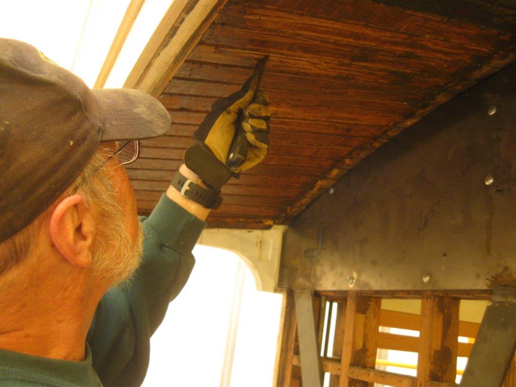
At some time in the past the south inner sill at the west end of the car had a new piece of sill spliced in.  The splice is just to the right of center in this picture.  There is an overlap of the old and new pieces extending to the right under the plywood.  Several bolts were placed through the splice that were removed when we installed the angle steel some time ago.  Now to replaced the bolts we must drill holes through the steel.


 In this photo John and Bob are doing just that.


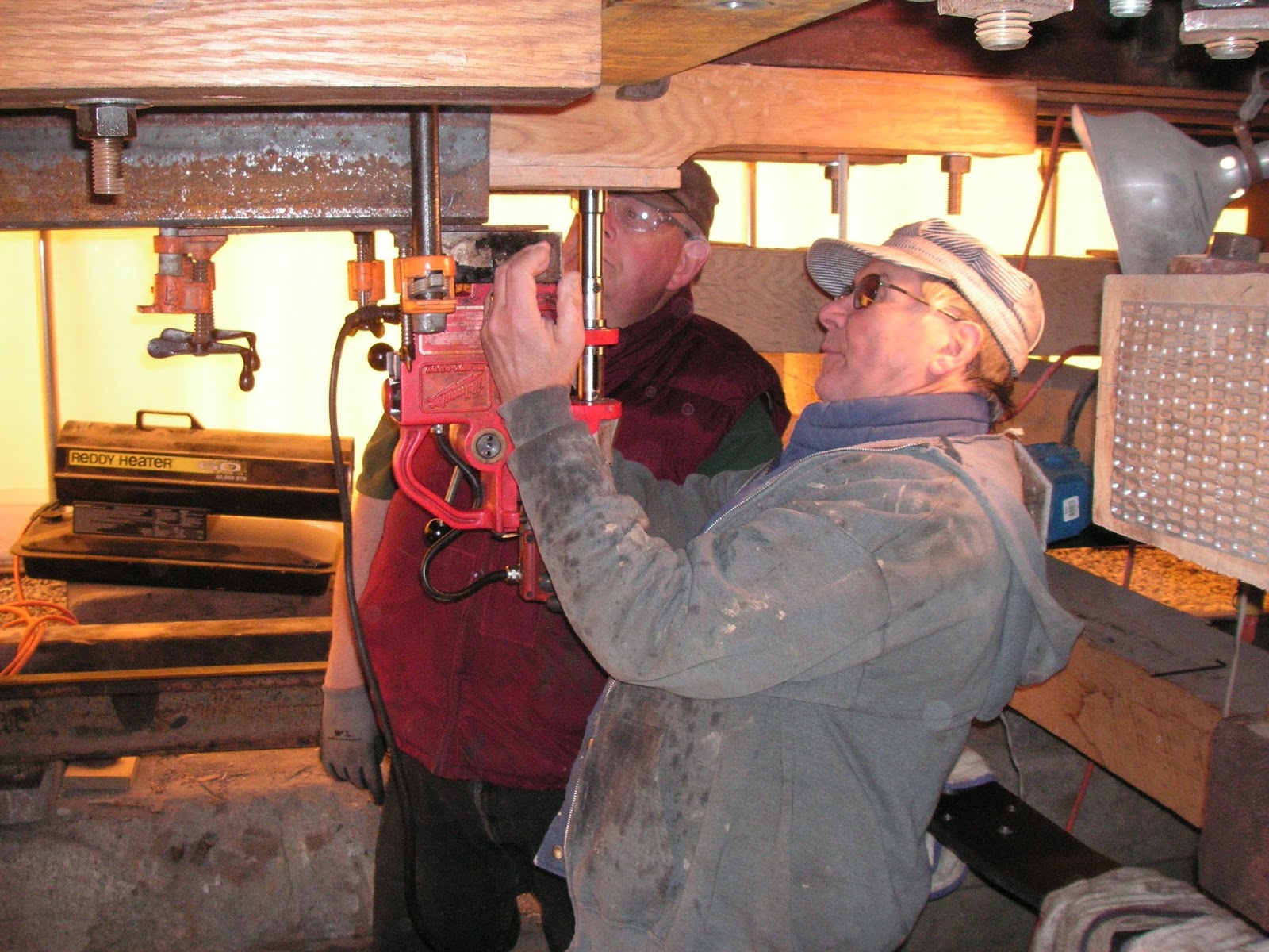
Additional bolts also had to be installed in the inner sills and bolsters.  Don is on top doing the holding and  Ron below.  An ongoing project this month also was to tighten all the nuts on the bolts in the floor framing prior to installing the underside sheathing, the next project.


We picked up the material for the siding on the car.  It is tongue and groove like what was removed.
 
The siding was cut to length at the worksite, and taken to Don's garage where he and Jim primed it.  This photo shows Jim and the finished product.
The lower end had to be beveled to fit the slope of the window sill.
This photo shows a panel that has been installed temporarily. The upper end fits into a slot in the letter board and the lower rests on the window sill.


This photo shows a part of the piece of wood that covered the end of the car above and next to the upper part of the door.  It was one piece that extended across the top of the door with a mirror image of this at the other end.  As you can see it was well secured with screws that were buried into the wood.


Craig has been busy duplicating this piece, and has elected to do it in three parts.  The curve of the roof varies across the width of the car which made fitting more difficult.  Here the two end pieces are held in place with clamps.  The metal is showing through over the door.


In this photo Craig is fitting the center piece of wood over the door.  Eventually these will be bolted through to hold them in place.


Just a little adjustment on the belt sander.


The back side was drilled to accommodate the heads of the bolts holding the steel plates in place.


This is the finished product.  A second (almost) identical piece is behind.


More drilling to fasten the wood in place.  Bill K. is reaching high overhead.


Ron is grinding off one of the bolts holding the steel as the threads are too short to tightly secure the plate to the framing.  They will be replaced.


Another project this month was installing the truss rod brackets on the needle beams.  Marshall reproduced these from photos of a similar car.  (See photo in February 2016 posting.)


The first thing was to plug and  fill the holes from the previous brackets.  Here Y. T. is tapping in a wooden plug.


Then the bracket posts were mounted on each end of the two needle beams.  Bob is tightening the bolts holding the post.


Then the bracing arm goes on and is lag bolted into the needle beam.  The paint has been removed from both pieces where they attach to each other prior to welding them together.


The next project was continuing the assembly of the end platforms.  This photo taken before the disassembly shows the tie rods holding the bracing and end pieces in place.  Note that the closest rod is bent down to pass through the bracing at the middle.  The exit hole in the end sill is higher than the hole in the platform brace.


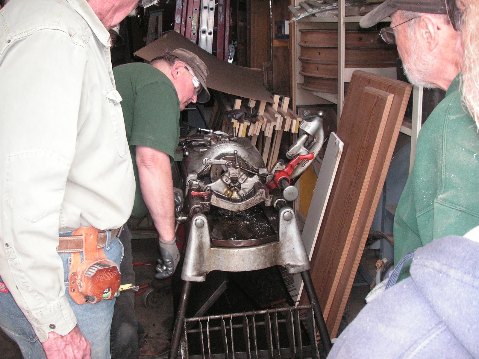
We borrowed the rod bender again from the Trolley Museum, consisting of a frame and hydraulic jack to put two bends in four rods.  The downward bend on one of the east end rods is being done here.  The west end ones were done previously.  Bob is exercising his left arm on the jack in this photo while John has positioned the rod in the saddle.


The rod has been bent sufficiently and the frame will be removed.


To put the upward bend in the rods the jack was removed and a portable hydraulic device was used as the jack would not work in the inverted position.  Here John and Don are working on a rod on the west end of the car.  Don has his left hand on the pump while John positions the hydraulic cylinder in the frame.


The end result, a double bend.


Tom then cut the rods to the proper length and beveled the end in preparation for threading.


Bob is using a hand threader in tight quarters.


It looks like we are ready to put the bracing piece and end piece back in place.


The bracing piece is installed and secure.  The bend in the rod is in the upper right corner of the photo.


Thanks again to Tom Simco for sharing photos.

Tuesday, March 29, 2016

March 2016 - Needle beams installed

We had two work sessions in March, the 3rd and 5th.  Most of the efforts were devoted to installing the needle beams as described in the previous post.

There were more holes to drill.  Existing holes were present in the sills but these had to be re-drilled through the steel angles that had been placed earlier.  Don and John are manning the drill.


This photo shows the bolts in place along the length of the needle beam where they have been placed through the sills.  Bill K. is tightening one of the nuts.  The truss rod has been put in position but not engaged with the queen posts or tensioned as yet.


Tom then cut the protruding ends of the bolts with his portable band saw.


Spacer plates were cut from stock to place between the beam and the intermediate and outer sills as the angle steel on the inner sills caused the beam to be lowered by the thickness of the steel.  Fortunately there was an easy way to do this with a mechanical saw.


The end bolts for the needle beams presented another challenge.  Notice at the far right side of this photo one of the vertical framing pieces has been cut and removed.  In the lower right corner a groove is present in the large plank where it meets the outer sill.  This is where the two end bolts were for the needle beam.  Part of the framing on the outside of the car had to be removed to access this area as well.


The solution was to use rod threaded at both ends inserted from the bottom.  Here one of the rods is being threaded by hand.


Here is yours truly at the bottom.  Getting the bolts through the beam, spacer plates, and sill was a bit tricky, but finally accomplished.


Then making room to thread nuts on the bolts was necessary.  Bill K. is wielding the chisel.


This photo shows the two end bolts in the needle beam secured.  Note the cut end of the framing member near the top of the picture.  The next task was to replace the framing that was removed for access.


This photo shows the needle beam with the two bolts through it and secured with a plate between the nuts and the beam.  There is an end cap over the beam with the truss rod passed through it and a nut to tension the rod.


Here is the final configuration with the truss rod in the grooves of the queen posts providing support to the center of the car.


The next step was to repair the damage caused by obtaining access to needle beam bolts.  Don is gluing the pieces together on one of the verticals that was cut.  Amazingly the cut piece didn't get lost.


Then metal plates were fastened to each side of the splice.


Finally the frame bracing that was removed was replaced.  Some of the pieces that were removed had to be replaced with new wood since they were damaged.


Concurrently, Bob was working on plugging the screw holes in the window sills.  Here he is cutting plugs out of a block of wood using Craig's plug cutter.
The plugs were then glued into the screw holes like so.
The plugs were then cut flush with the window sill using a fine saw with no kerf so as not to scratch the sill.


Finally, Bill L. continued work on removing paint from the overhangs.  First with a heat gun,


then with a scraper.  Looking good, Bill.

Thursday, March 3, 2016

February 2016

We worked on the needle beam hardware under the car.  These help support the center of the car along with the truss rods that run longitudinally from bolster to bolster.

Here is another look at the drawing of a similar car showing a needle beam which has been colored red.  (Click on image to enlarge.)  The needle beams also have rods under them fastened on the ends, with queen posts placed along the length in a similar configuration to the truss rods in this drawing.

This is a copy of a photo of the needle beam hardware configuration (click to enlarge).  Arrow #1 points to the longitudinal truss rod.  Arrow #2 points to the needle beam.  Arrow #3 points to the queen posts (2) attached to the needle beam.  Arrow #4 points to the truss rod along the needle beam.  This geometry provides support all along the width of the car as well as at the ends of the beam.

This photo shows Bob and Bill K. contemplating one of the needle beams on our car with the queen posts attached.


The rods need to be bent in two places where they are in contact with the queen posts.  So out comes the "bender" again.  Bill K. looks like he wants to do some bending, but where is the jack handle?


Tom is cleaning up the ends of a rod on the belt sander.


The rods are threaded at each end and tension applied by tightening nuts.  Here the crew is learning how to use the threading machine.

Friday, February 12, 2016

January 2016

We had four work sessions in January even though the one on the weekend after New Year's was cancelled.  We are working the Thursdays before the regularly scheduled Saturdays for a few months to get caught up from weather cancellations, etc.

The platform tie rods are mostly in place but all are not yet drilled through the platform end sills.  There are six rods in each platform with three on each side.  On the right side of the picture shown one can see a rod along the inner aspect of the outer sill, and two next to the inner sill.
The rods had to be bent some to be threaded through the sills of the car.  Some were bent by hand, but we borrowed a hydraulic bender seen here.  There is a jack below pushing up on the rod between the black guides to force a bend.  A little bit of Bob's arm can be seen in the lower left of the photo as he pumps.  John is guiding the rod into the grooves.


One of the rods next to the inner sill is hooked on to the bolster as shown here.


The other rod near the inner sill is hooked on to the end sill of the car as shown here.  It is fixed in place with a lag bolt.  The rod attached to the bolster is seen just above the hook in the upper left corner of the photo.


The third rod which is along side the outer platform sill is threaded on both ends.  This photo shows the rod passing through the end sill of the car and a washer and nut will be used to secure this end of the rod.


More drilling was needed under the car in the pivot plate.  John and Tom are positioning the magnetic drill to do the job.
This photo shows the drill in place attached to the steel plate by the magnetic base which is activated electrically.
This photo shows the window hardware for the lower level windows.  The larger piece on the left is a latch that attaches to the side of the frame and holds the window open or closed.  The smaller one on the right is a handle that goes on the bottom of the frame and is used to raise the window.  These are original pieces from the car, but some are missing.  They are still available from the original company but the current latches have two screw holes in the top instead of one.


In order to accommodate two screws on the side frame the strips holding the windows in place were removed and cut narrower to expose more of the frame.  Here one of the strips is being replaced after being downsized.


Craig brought a mockup of a clerestory window that he built for display.  In this photo the window is open about halfway (toward us) being hinged at the bottom.  The mechanism on the right holds it in position.  There is a pull in the middle that has a hole in it for a hook on a pole to position the window as needed.


Here is a closer look at the retaining latch for the window.  There is a spring loaded plunger that rides on the notched bar to hold the window closed or open various amounts.


Work on the roof decking and trim is winding up.  Craig is preparing to install one of the last pieces of trim on the curved end of the clerestory.


And on it goes.  It will be smooth as well.
This is a photo of the end of the car before dismantling showing a cabinet over the door.  There were two of these, one at each end.  One of the doors was off in the cabinet at the other end of the car but the hardware was present.


Craig made new doors for the cabinets and Don cleaned up the frames and mounted the hardware as shown here.


In this photo Debbie is oiling the back side of the cabinet with linseed oil.  The front facing into the car will be finished like the rest of the interior.


The exposed framing of the car is being oiled as well, both old and new.  Here Bill is working on the sills from underneath.


Thanks again to Tom for some of the photos.


Followers

Blog Archive