Friends COS calendar

A subset of the Friends of the Cumbres and Toltec Scenic Railroad located in Colorado Springs, Colorado, with the mission of preservation, restoration, and interpretation of CTSRR historic assets. The Springs group is primarily involved in restoration. See below for blog archive of older postings.

Sunday, March 24, 2019

January-February 2019

The bolster bowls/plates were finally installed during these work sessions and we started on the installation of the flooring.  End railings were fitted and contract roofers began installing the copper roofing.

The flooring is douglas fir and has been stored in a box car belonging to the Trolley Museum.  John and Mike are stacking these boards prior to squaring the ends on the chop saw in the background over Mike's back.


John is cutting while Jim is helping move boards.
The boards were then placed in this jig for notching.


Craig used his router to cut the notches.


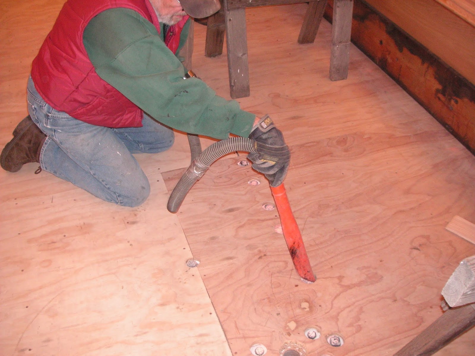
Bill L. vacuumed the subfloor.


The next step was placement of tar paper as a moisture barrier.  Dean is working on this while others are wrestling with the bolster bowl.


A string was used to align the first row of boards.  John C. is shown here helping with the placement.


The first row was face-nailed down, here by Dean.


The tongue and grooves were fitted and the splines inserted into the ends of adjacent boards.


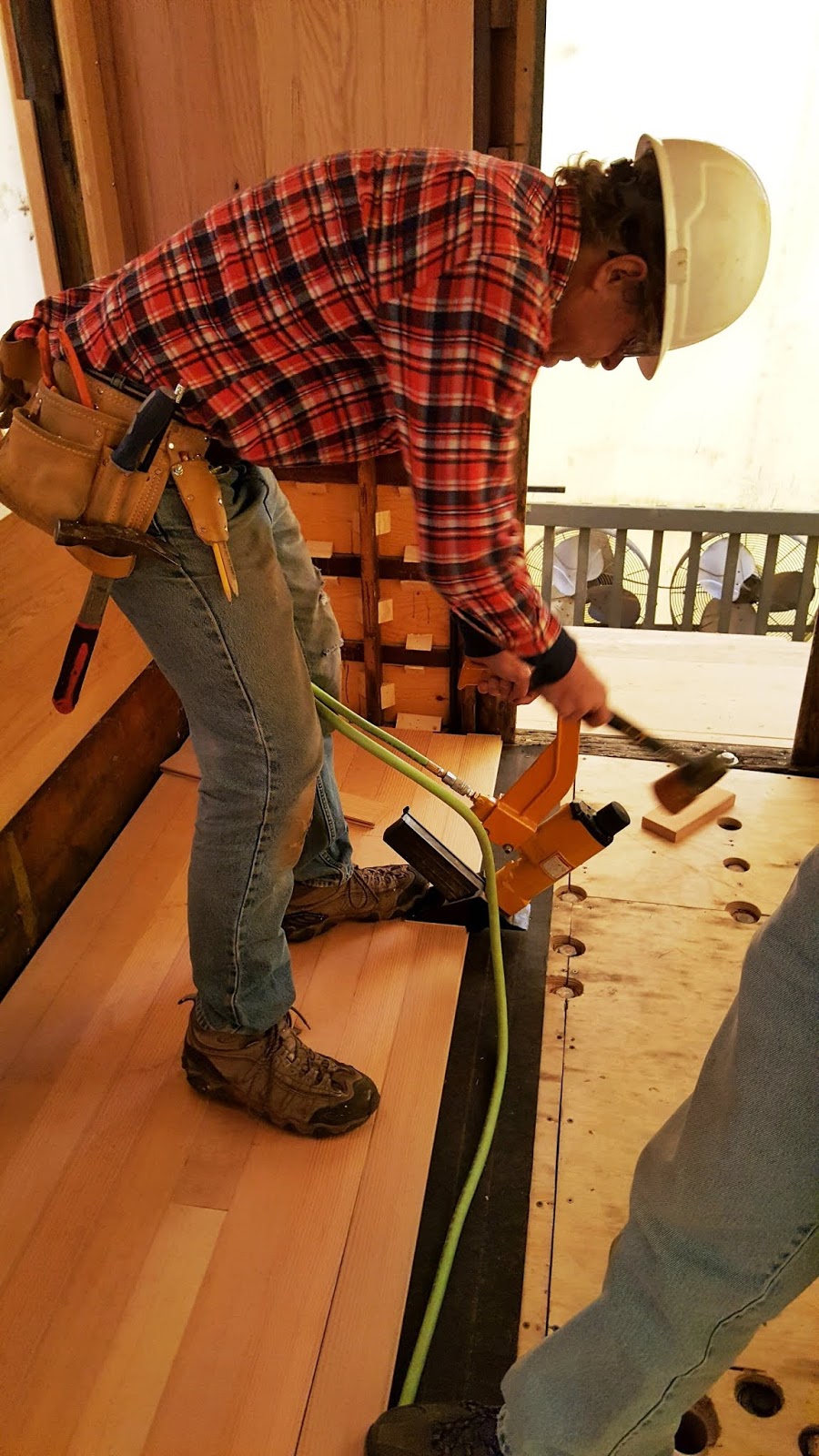
After the first row was installed the subsequent rows were nailed in place with a flooring nailer.


While trying to place the bolster bowls on the bolsters it was discovered that the ends of the platforms sills (and covering steel) were not allowing the bowls to seat properly.  So grinders were used to cut away the offending wood and steel, here by Mike.


In this photo the bolster is in the upper right corner and the two platform inner sills extend off to the left with part of the ends removed.  The bowl is resting on the tie or block below.


Now it fits!  The plates are heavy and work space was limited so mechanical assistance with lifting and holding was needed.  Bill K. and Mike are aligning the plate with the bolt holes in the bolster.


It looks like Mike is putting a lock nut on a bolster bolt.  This was a two person job with one above having a wrench on the head of the bolt in the floor to keep it from turning.


Sometimes the bolt holes didn't line up properly and redrilling was required.  In this photo Bill K. is looking cautiously at the magnetic drill that is attached to the bolster to redrill one of the holes.  The rope is to hold the drill from falling if the power were to go off (which it did).


This photo shows the bolster extending from the upper left to the lower right part of the picture.  The plate (or bowl) is attached with bolts extending up through the floor of the car.  Part of the bolster wedge is visible in the extreme upper left of the photo.


The plate clears the end of the platform sill that has had a haircut.


Four bolts hold the plate in place.  Coupler nuts were used because of the carriage-type bolts in the plate.


A view from below showing the four round head bolts that have been ground flush with the surface of the bowl so that the truck can turn on it.  The two bolts on the ends are for the bolster.  The hole in the middle is for the king-bolt or center pin.


This plate covered the hole in the floor of the car through which the center pin was placed, and was recovered during dismantling.  Only one was left in the car and plans are to have a second one made.


The platform end railings were fitted during this time which are secured in place with bolts through the platform end sills.  The sills were marked for drilling.


"Joe The Welder" made the hardware for the railings.  Shown here are posts which are tapered slightly, double threaded bolts, and washers.


The bases of the posts are threaded internally for the bolts, which pass through the sills and are secured with nuts underneath.


Drilling is a two person job with one guiding (Bill L.) and one drilling (Dean).


In this photo the double threaded bolt is being put into one of the posts by John C.  The rail is at the top of the photo with two posts attached to it.


Everything fits.  The railings will be removed for painting and reinstalled later.


The roofers have been at work installing the galvanized copper roof.  They are professional roofers on contract and have been doing a great job.


The material comes in sheets which are locked together.


Vents for the oil lamps will be replaced.


Coming together nicely.


This photo shows the detail of the fitting around the clerestory.


The vents are soldered to the roof panels.


Meanwhile, Craig has been working on the window glass.  The car originally had regular glass but now tempered glass is being installed.  The moulding needed to be adjusted accordingly and this photo shows a floor spline, about the same thickness as tempered glass in the revised moulding.


Craig did two trial windows with the tempered glass which looks like it fits perfectly.


This photo shows a detail of the inside at a corner.  The windows raise up and latch open for ventilation.


Here is a window in the open position.  There are several stops to open the windows various amounts depending on the amount of ventilation desired.


The doors needed to be installed before the interior trim could be completed.  Here from left to right John C., Dean, Craig (on the other side), and Mike are working on the east end door.


Craig is placing the screws in the door frame.


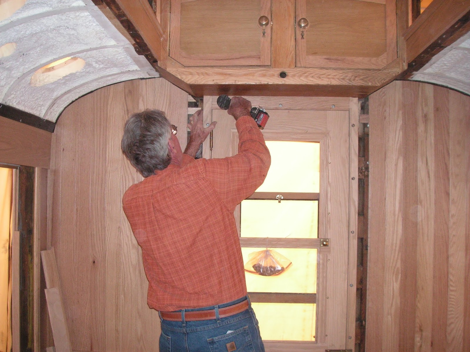
It looks good open and closed.


Thanks to John Engs, Tom Simco and Don Atkinson for contributing photos.

Saturday, February 16, 2019

November-December 2018

Late fall saw work continuing on the coupler pocket and seat frames, and starting on the flooring and end platform railings.

The seat frames are cast iron and will need some cleaning up of burrs and ridges as well as removal of the legs for the outside frames along the wall.   Craig, Tom, and Dean are planning course of action.


Craig points out a ridge in the frame and there is a grinder that will be used to clean it up.


Sometimes a bigger grinder is needed.  It works best with two people, one holding and one grinding.  Here Don is grinding and John holding.


We began fitting the end platform railings and posts.  This photo shows the railings that Joe has made.


These are the posts for the railings.  They also were made by Joe and are threaded at each end and slightly tapered.


The car originally had roof vents for the oil lamps and for the restrooms.  This is a photo of a photo of a few of the vents that were present originally over one of the restroom areas.


We have diagrams of the restroom (or "saloon") layouts as shown here for the men.  From this the location of the roof vents was calculated.


First measurements were made on the floor to locate the fixtures in the restroom.


The floor locations were used to determine where the vents should be located, in the process avoiding roof framing, etc.  Here Don and Craig are carefully measuring.


A pilot hole was drilled, then a larger hole was cut with a saber saw.  The edges were trimmed and filed so that the vent would be in an erect position on this curved roof.


It looks pretty good, guys.


We started on the flooring although installation has to wait for the bolster truck bowl or plate to be installed, a tedious process to be covered later.  In this photo Craig is positioning a floor board in the jig he made to cut a notch in the end of the board.  Each board will be notched in the ends and a spline or biscuit inserted to keep the ends from moving in relation to each other.


This photo shows how the ends of the boards will be stabilized.


Here Craig is routing the groove in one of the boards.


This photo shows Joe on the left with the two red spring pockets that he made.  An original one is to his left in front of Don while Bill K. looks on.  These go under the car attached to the steel angle brackets that have been installed at each end.  There is a diagram of this mechanism in the posting of Jan.-Feb. 2018.  The coupler attaches to this with a heavy spring which allows for some resilience when coupling cars.


Work also continued on installing the bolster truck bowls, one of which is seen here next to some vent caps.  It is upside down as it rests on the table.  The side we are seeing rests on the truck of the car and allows the truck to rotate.  The bolts holding it are carriage-type, recessed into the plate so that the surface is smooth.


This photo shows the plate right side up.  The body bolster fits into the groove where the two bolts are resting.  The large hole in the center is for the king pin which will extend through the bolster into the truck, and is the center of rotation of the truck.


Here the plate is positioned just below the bolster with bolts extending down to it through the bolster.  John and Don are marking the plate for drilling two more holes, one at each end, necessary to clear protruding bolts.


Don is marking the plate.  The brackets for the coupler mechanism are to Don's right.


The bolt positions have been marked and now the hole size is being drawn on the plate.


This is a view of the floor above showing the larger hole for the king pin and the six bolt positions corresponding to those in the bolster and plate.  Once the bowl/plate has been installed the flooring can be laid down over this area although there will be an access hole left for the king pin.  The original metal plate that covered the king pin was removed during dismantling and has been saved.  It will be re-used as well as used as a pattern for casting a second king pin cover.


Bill K. is looking toward the coupler pocket brackets from the end of the car.  The brackets have threaded rods through each end which were used in positioning the  brackets so they are parallel to and opposite each other.

Followers

Blog Archive